
The NCL2000 Project
by KC5RT
or how to convert 400 dollars into a KW.
04/01/2015 Updates: KM4DR provides blower motor and fan repair / replacement information down load it here.
I was looking for a 2KW amplifier a few years ago, and I did a bit of research on the NCL2000. I found it to be a real work horse of a desk top amplifier with a strong power supply and two ceramic tubes working in parallel. So when I came across one at the Joplin Hamfest in 2010, I decided to invest in a non-working unit with three sets of tubes. At the time 400 dollars seemed reasonable. Well the old girl has been in my garage waiting for three years for someone to take a look at her. That time has come. The amplifier can operate on 110 or 220 and since my work bench only has 110VAC I re-wired the amp for 110Volts and started the initial checks.
I knew that I would be replacing the usual suspects, HV diodes, filter caps, and equalization resistors, and maybe a relay or two. So I first removed the capacitor / rectifier board that is located under the chassis. The old filter caps were all leaking and showed signs of age. These were originals that were now 45 years old. Also all of the equalization resistors were bad. Instead of reading 50K they read anything from 70K to 120 K. These 5 watt 50K resistors can be found at Mouser electronics for about $2.50 each. You will need 8. The filter caps are 80 mfd at 450 volts and I purchased 10 Sprague caps that would fit in the clips on the board. The two 5KV diode assemblies were suspect but both read OK. I decided to change them out anyway with strings of five 1N4007 diodes. There is another 80 mfd 450 volt capacitor (C31) in the screen supply that was also changed out. It too was 45 years old.
With the HV power supply board removed from the amplifier and the HV wires from the transformer tapped up, I decided to apply power and see what smoked. To my amazement the fuses didn't blow, the filament and low voltage AC supply was working and the time delay relay timed out at 60 seconds. I got the ready light and it was now time to try the HV transformer. Keeping my fingers crossed and my left hand near the power plug I throw the high voltage switch. Wow, relays clicked and the red light came ON and there was no smoke. I had previously shorted out the interlock on the top of the front panel so that the HV relays would latch. Now to check some voltages. First the screen voltage, it was 250 as per the manual for CW operation. Next the grid bias. It was zero. Darn ! The grid bias must be between -25 and -45 to set the idle current to 225 ma in SSB mode. This power comes from a winding on the low voltage transformer T2. So here is where my first troubleshooting work will begin.
The bias supply on this amplifier is like nothing I have seen before. It consists of two PNP high voltage TO3 transistors and a zener diode in a voltage regulator circuit. These components are under the chassis except for the TO3s that are under the Tuning capacitor. You have to remove the right hand gusset to reach these. With the power ON and only the ready light ON, I began looking for the -90 volts that feeds the regulator circuitry. It wasn't there. Suspecting rectifier diodes CR1 and CR2, I did a quick continuity check and found both diodes OK. That wasn't a good sign. It could be the transformer, but after removing the diodes and checking the AC voltage which was 127 VAC I had to look for a short. I found it a few minutes later when I removed the terminal from Q1's collector. Q1 was shorted to ground at the collector. Zero ohms. It was a failure of the mica insulator under the transistor. Removing the transistor and replacing the insulator fixed the dead short. Now to reassemble the wiring and give it another try. As luck would have it, the regulator was working. I could adjust the bias supply from -25 to -45 VDC using the control on the back panel. National made the bias measurement easy by providing a bias supply test point on the back of the amplifier.
I now suspect that this was the main culprit it the amplifiers failure. With the grid bias at zero the tubes would have conducted strongly and tripped the over current relay removing high voltage from the tubes. Below is the schematic of the bias regulator. This small failure resulted in the amplifier being taken out of service and left to sit on a shelf for about 10 years according to its previous owner.
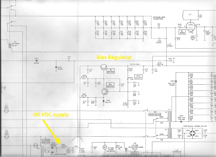
The bias regulator and the screen grid supply now check good. While I wait for the HV power supply components to arrive, I will check out the metering circuits and look for any HV leak paths or defective bypass capacitors.
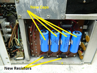
Update: The parts arrived from Mouser and below you can see the updated rectifier/filter board. This board must be removed from the amplifier in order to reach the components on the top of the board. A total of eight 80 mfd 450 volt capacitors and eight 50K 5 watt resistors will be required. The resistors are part number 71-RS00550K00FE12. These are smaller than the originals in physical size but have the same rating. In the photo below you can see the finished and installed board.
I strung together two sets of five series connected 1N4007 diodes to replace of the original rectifier modules. (CR8 and CR7). These are on the top of the board and not shown in the picture, however, you can see the screws that hold the insulated standoffs that I used to anchor the 10 diodes.
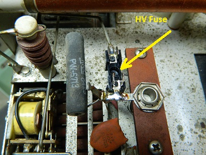
In addition to rebuilding the rectifier board, I added a small fuse holder in the HV line. Even though the power supply has a HV overload relay that shuts down the transformers primary when an amp of plate current is exceeded, I decided a small 1 amp fuse couldn't hurt. Note the fuse holders placement on the top of the chassis.
Now that we have the HV power supply reassembled it's time to test it. First make sure you place an insulator disk (plastic washer) between the spring loaded "dead man" interlock and the HV test point. You can see it in the photo below just right of the new fuse holder. This is where the plunger stick will go after you are ready to reassemble the case.
Make sure the amplifier is not plugged in at this point. Keep in mind if all goes well you will have 3000 volts inside the chassis and it can kill you. So caution is advised.
It's time to put some fire in the wire. Insert a 1 amp fuse in the new fuse holder if you installed it. Next attach a dummy load to the amplifiers output. Then connect a keying switch to the back panels keying terminals. I use a push button that returns to open just in case I need to unkey quickly. Connect a DVM to the bias test point and ground so you can read this voltage. Now plug in the amplifier to either 110 volts or 220 depending on your set up and set the SSB/CW switch to SSB. Set the Multimeter to read plate voltage.
Turn on the main power switch and wait for the ready lamp to light. (About 60 seconds). Once the ready lamp is ON, measure the grid bias voltage and adjust it to -40 volts using the pot on the rear of the amplifier. You are now ready to see if your HV rectifier repairs are going to work. If a tube is bad the new fuse may blow and could cause a bright flash so don't look directly at the fuse.
Stand back a bit and turn ON the Plate Switch. If all goes well and no fuses blow or relays kick off, observe the Plate Voltage reading on the internal multimeter. It should read 3000 volts. Also quickly look at the plate current meter, it should be zero millamps. If its not zero then you have a tube issue or a bias issue. Turn off the plate voltage or the main power switch. If however, all goes well then it's time to set the bias. Key the amplifier using the attached keying switch. Observe the plate current and adjust the current to 225 ma using the bias pot on the back of the amplifier. Record the bias voltage reading and only key the amplifier for short 5 to 10 second periods. The bias voltage should be between -35 and -40 depending on how good your tubes are. Higher is better.
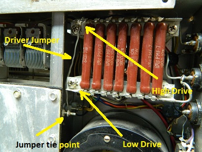
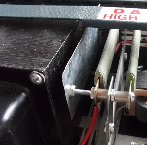
Well if you got this far you can turn everything OFF and connect up an exciter. Make sure you check the input swamping network to see if your amplifier is set up for a high or low power driver. Check the manual. High power (normal 50 to 80 watts) drive requires the jumper to be placed on the far left tie point. See the photo below.
Now follow the tune up procedure as outlined in the manual. Always tune up in CW mode. Instead of just dipping the plate current as in most amplifiers you must also watch the multimeter in the screen current setting and tune for max the screen current. At no point should you allow the screen current to go above 40 ma. It should max out at 15 to 25 ma. If it does go above 40ma increase the load capacitors setting. Tune in short burst of 5 seconds or less. If SSB is your preferred mode, after CW tune up turn OFF the plates, select SSB and turn the plates back ON. No further tuning is required but some minor touch up may yield a best tune.
Never Change bands while the exciter is keyed or the plate voltage is ON. Never change modes with the plate voltage ON.
As a special note: In the National Customer Service Bulletin dated July 6, 1966 there are several circuit improvements but perhaps the most important is the parasitic suppressor redesign.
Wow what a power house amplifier this is. Time to clean it up and paint the case and reassemble.
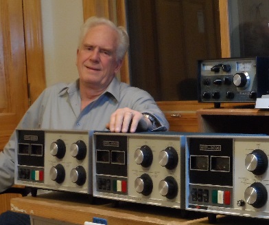
Ken NØCA has many of these amplifiers, he is a self proclaimed "NCL junky" and has provided a few tips below.
See Ken's QRZ page for insight into the meter shunt repair.
In the photo to the right you can see Ken and his many fine NCL2000s.
Below are some important improvements submitted by Ken NØCA and check out the information supplied by Gale KM4DR on the blower.
"Here are ideas I have used to keep my beautiful NCLs on the air"
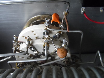
The Bandswitch: I think bandswitch arcing might be caused by dirty or weak antenna relay contacts. In any case, the bandswitch can arc between the 40 and 80 meter contacts on the front rotor. Note that the contacts burn not at the closest point between contacts, but at the thinnest parts of the contact. Also, only the rear contacts on the front rotor are affected. This indicates some kind of corona discharge rather than hard arcing. I have stopped this problem by adding a 7pF cap between these contacts to bleed off any corona. To further protect the contacts,I have created a second but smaller gap between the contacts to arc over at a lower voltage and save the contacts if an arc occurs. Just solder a 14 ga. solid wire to the wire connecting the 40 meter contact and bend it to cross the 80 meter contact wire at a right angle. Bend the wire so that the gap between them is less than the gap between the contacts on the bandswitch. If an arc occurs, it will arc between the copper wires and save the contacts. Just make sure the new gap is smaller than the gap between the contacts on the bandswitch and that the wires cross at 90 degrees for the best reliable arc gap. The copper wire is tough enough to survive many arcs if they occur.
Transformer heat reduction: The bleeder resistors are remounted higher and farther from the transformer with a reflector between the nearest bleeder and the transformer. This setup REALLY lowers the transformer temperature. The bolts in the picture are 8-32 X 2".
The Fan: Most fans are easily fixed by inspecting the rotor spacers. The rotor is spaced from the bearings with a nylon spacer on each end. Since the fan shaft is vertical, the lower spacer takes the weight and wears against the lower bearing. This wear occurs on outside of the lower spacer. The rotor wears a groove in the lower spacer and eventually rubs against the lower housing. Simply switching the lower and upper spacers can restore the fan. Sometimes just reversing the lower spacer will work. This has fixed all my fans.
Some National NC2000 History / Specifications
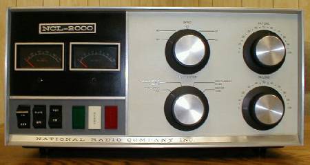
The NCL-2000 was National's desk top 2000 watt input linear amplifier designed to work with their solid state HF transceivers or any 20-200w class, 50 ohm transceiver. To quote National; "Every component on the NCL-2000 is rated for operation at a "DC" kilowatt, if you want to check power output you'll need a bigger wattmeter then those now available on the amateur market." On any band the '2000 will pin a meter that only reads 1000 watts full scale.
Addition of the NCL-2000 allows you to run at the maximum power allowed by law. The two 8122 ceramic tetrode output tubes were designed specifically for SSB, and provide 800 watts of plate dissipation to assure conservative operation. Not only does the NCL-2000 deliver the power, but it does it cleanly. Third and fifth order distortion products are down 30 to 45 db, hum and noise down a minimum of 40 db. Operate in areas of high humidity? Don't worry about power supply or plate circuit breakdown. The '2000 is rated for full output at 90% ambient humidity
The amplifier was produced from 1964 until 1972 and nearly 5000 of them were built..
FEATURES:
•2,000 watt PEP input on SSB, 1000 watt input on CW, RTTY, or AM.
•Equal power output on all bands 80 through 10 meters.
•Completely self-contained desk-top package with built-in power supply.
•Exclusive grid-controlled AB2 operation for high efficiency and linearity.
•May be driven to full output with any exciter delivering 20 watts to 200 watts PEP
• Passive grid with internal 50 ohm exciter dummy load and relative exciter output indication for simplest tuneup.
• All necessary relays built in for transceiver or transmitter-receiver operation when desired.
•Instantaneous switch over to exciter
•ALC output.
•Separate precision plate and multimeters.
•Most complete safety and overload protection, including
1 minute time delay relay, overload relay, lid interlock and automatic
shorting bar.
A.C. POWER:115VAC 60hz single phase at up to 15AMPS or 230VAC at up to 7.5AMPS.
SIZE: Completely self-contained, including power supply, in desk-top cabinet (dimensions only 7 5/8" H, 16 1/4" W, 12 3/4" D) with a weight of 62lbs.
DRIVE REQUIREMENTS: Adjustable passive grid input and use of high power ceramic tetrodes in final permits drive to full output with exciters delivering as little as 20 watts or as much as 200 watts.
OUTPUT MATCHING RANGE: 40-60 Ohms.
METERING: Separate rear-illuminated precision D'Arsonval plate and multi-meters for simultaneous measurements.
ALC: ALC output to exciter for maximum talk-power with greatest linearity.
CLASS OF OPERATION: Grid-regulated AB2 permits easiest tune-up, low drive power for maximum exciter linearity, and protection from destructive peak currents.