
10-80 USB,LSB,CW
10 tube hybrid rig 500watts PEP, 300watts CW
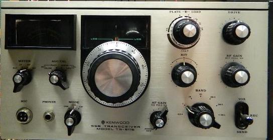
Click here for a copy of the TS511S Manual.
Click here for a copy of the TS510 Service Manual (very helpful when aligning the 511)
Click here for a copy of the TS510 power supply (Same as 511 supply)
The TS511 you see here was a gift from a good friend. The radio had a
few unusual issues when I got it but it did receive and it did transmit
albeit with low power and some erratic behavior. The radio's design is
quite simple yet ingenious in the way it uses some stages for both transmit
and receive. Since both the receiver and transmit seemed to have gain
related issues, I decided to focus my troubleshooting on the common stages.
The first IF stage and the S meter circuitry was number 1 on my list.
I decided to attempt a receiver alignment. I noticed that the radio seemed
to lack sensitivity and it wasn't long before I found the initial problem.
T4 the output IF coil in the 1st IF stage was broken. The core had been
cracked in two. This caused the coil form to twist when any adjustment
was made. The results of course was a broken wire and an unusable T4 transformer.
I removed the transformer and attempted a repair, but it was too far gone.
I would need a replacement T4. A google search didn't yield much help
and all of the radio chop shops had TS520 parts but no TS511s. Some never
even heard of a TS511. I decided to build my own T4 transformer. Since
I knew the IF frequency and the value of the capacitors in parallel with
the coils, I calculated the inductance of each winding to be near 34uH.
I also had the old coil and I counted the turns. IN a few days I had an
electrically similar but physically larger T4 coil to try. I put the coil
in place and realized I had built the coil backwards with the cold ends
close together. So back to the work bench do some rewinding. Once that
was fixed and the transformer installed I started to tune the receiver.
The homebrew T4 would not tune in the secondary coil. I had to remove
about 10 turns and try again. This time the receiver sprang to life. The
slugs turned the IF and the radio seemed to be on the mend. My quest for
a real T4 continued until just a few days ago when Katsuhiko, JA3ECA in
Nara, Japan offered to provide a salvaged T4 from his TS511S. See the
photo below of Katsuhiko's IF board with T4 removed. I can't wait to install
it and see how close my homebrew coils came to the real thing.
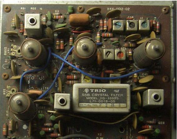
Tuning the TS511 is much like tuning a TS520. The bank of coils shown in the photo below must be tuned in the correct order or the alignment will not work. If you look at the circuitry closely, the coils in the mixer, and RF front-end are in series. They are not selected as individual coils but as sections of a larger inductance. If you try to align the radio out of order you will never get the best performance. The manual for the TS510 that is available on this web site gives the best directions. Follow the sequence of Bands to be aligned and you should see excellent results. Always align the Lowest frequency band first. In this case the 80meter band. Then go to 28-29 MHz and follow the bands in sequence to 7MHz.
This radio has quite a few variable resistors or POTS that are of the poorest quality. Many in my radio had to be replaced. The S meter sensitivity POT could not be adjusted, the CW unbalance and SSB balance POTs were also bad. I replaced these with new parts form Mouser.
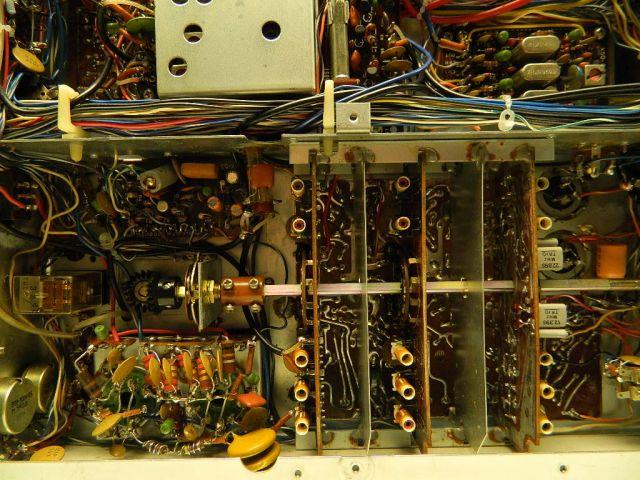
Here are the coil banks. Refer to the manual to obtain the band information and follow the band tuning sequence.
Here is a picture of my home-brew T4 and the top side of my TS511S.
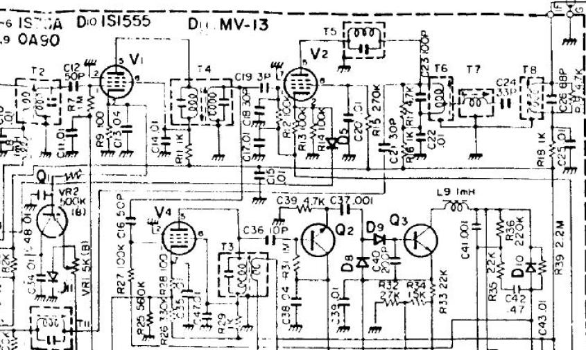
In the schematic to the right you can see the IF stage V1 and the T4 coils. This stage operates both in receive and in transmit. Its gain was about 20dB low due to the broken secondary winding and it could not be tuned or repaired.
Another tricky little circuit is the 8.595 MHz bandpass filter made up of T6 / T7 and T8. These coils also work in both transmit and receive and require a sweep generator to properly align. Unless you suspect this filter to be tweaked by a previous abuser leave it alone.
My filter had seen the "golden screw driver" so it was required to perform an alignment. Refer to the TS510 service manual.
Here is a photo of Katsuhiko's IF board. As you can see he has already removed the T4 transformer.
Katsuhiko emailed me and explained that he had already shipped the transformer via EMS and I should see it shortly. Wow, he was correct. The transformer arrived just 4 days after his first email
Now to install the transformer and complete the IF stage tune up.
See how close my homebrew coil came in the next section.
Also more to come as we troubleshoot the very powerful transmitter section
and the matching TS511 power supply.
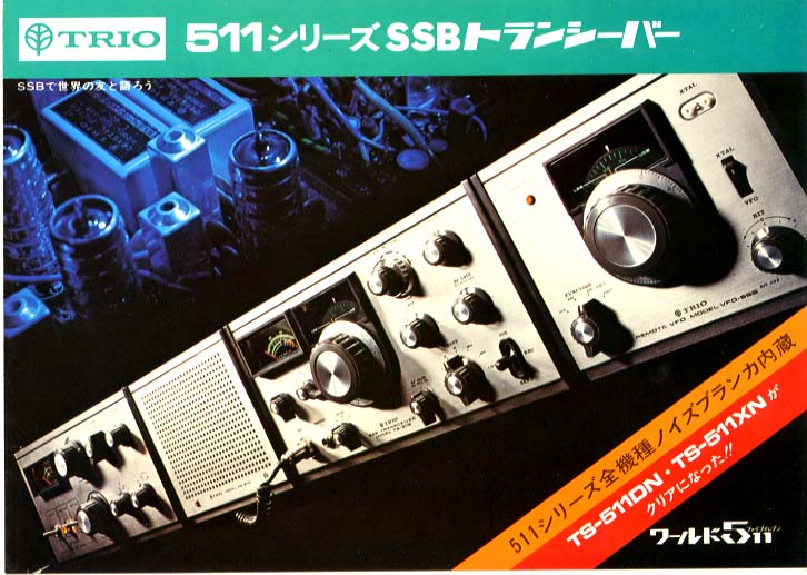
Also provide by Katsuhiko, JA3ECA, exN8EYH
in Nara, Japan is this brochure of the TS-511DN and the TS-511XN Accessories.
Regarding this brochure of TS-511, Katsuhiko tells me that the left most
unit is a 'TL-911' Linear Amp
which is pushed by five tubes of 6LQ6 for 2KW input.
Trio and Kenwood released four Linear amplifiers, TL-388, TL-911, TL-922
and TL-933.
Look closely and you will see T4 in the top left.